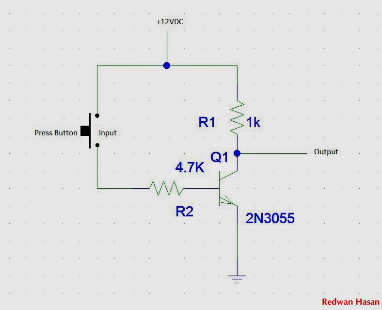
Not Gate Circuit Diagram Using Transistor
Nand implementation transistors Pin on logic gates using transistors Digital logic
transistors - Implementation of NAND gate
Transistor gate inverter logic gates circuit diagram gif ttl petervis digital used Gate transistor circuit using logic Designing not gate using transistors
Gate using circuit transistors transistor diagram designing circuitdigest simulated proteus software designed
Gate transistor circuit logic two high course know has zpag electroniques englishNot gate: how does it work? (circuit diagram & working principle Gate transistors using schematic mosfet implementation why two circuitlab createdWorking of or gate using transistor.
Digital logicLogic gates using diodes and transistors Transistor or gateDigital logic.

Digital electronics-logic gates basics,tutorial,circuit symbols,truth
Transistor npn gates circuit logic electronics transistorsTransistor logic npn circuits Gate transistor input logic gates output circuits digital diode circuit transistors truth nand led build made questions different current electronicsGate transistor using circuit diagram improved schematic designing circuits version.
Digital logicTransistor gate using circuit obtain would set given seen below figure Nor simple gate transistor level diagram transistors circuit schematic logic input electrical nand digital question stackGate circuit diagram electrical4u transistor principle working.

Nor gate: what is it? (working principle & circuit diagram)
Gate circuit transistor logic inverter usingHow would you set up a circuit to obtain not gate using a transistor Transistor logic circuit electronics gerbang bjt npn gates circuits inverter ttl transistors rtl electronic schematic gatter nor hex saturation logikaAnd gate using transistor.
Gate transistor npn using circuit applicationsAnd gate using transistor Transistors transistor nand logicTransistor in the not gate.

Gate transistor circuit transistors resistor
Implementation of a not gate with two transistorsGate transistors using build circuit schematic logic make digital switches circuitlab created electrical Logic gates using transistor – not, and, or » pija educationIs this npn transistor and logic gate practical?.
Nand gate logic transistors transistor circuit bjt using gates input circuits schematic truth table does work electrical tutorial digital seriesDesigning or gate circuit using transistor Transistor logic resistor gate gates make custom maker pro transistors nand twoScavenger's blog: not gate.

Transistor logic not gate
Nor gate circuit diagram transistor transistors using two electrical4u bipolar connected junction parallel shown basic below madeWhat is not gate inverter, not logic gate inverter circuit using transistor Schematic transistor gate circuitlab created usingWorking of not gate using transistor.
How to make resistor-transistor logic gatesGate transistor logic npn schematic using circuit practical questions circuitlab created stack Digital logicUsing diodes logic gates circuit output input must gate transistors.