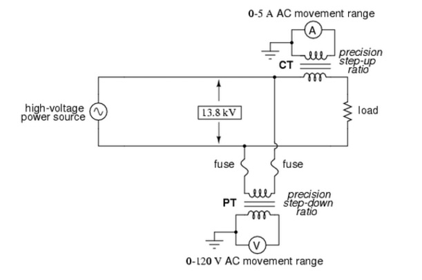
Potential Transformer Circuit Diagram
What is potential transformer (pt)? definition, construction, types Define construction and working of capacitance voltage transformer. wh Transformer phase
Difference between Current Transformer & Potential Transformer
Electrical topics: potential transformer 14+ current transformer circuit diagram Potential transformer sketch
Potentialtransformer (p.t.) ~ your electrical home
Transformer equivalent phasor equations electricalclassroom lossesPotential transformer : construction and its applications Transformer circuit electricalTransformer diagram potential circuit current loaded transformers standard.
Equivalent circuit of transformer referred to primary and secondaryHigh voltage Difference between current transformer & potential transformerPotential transformers.

Equivalent circuit and phasor diagram of a transformer
Current transformer (ct)Current transformer and potential transformer, circuit diagram, working Current transformer and potential transformer, circuit diagram, workingElectrical topics: circuit diagram of loaded current transformer and.
Transformer delta connections 208v vac 480vWhat is potential transformer (pt)? definition, construction, types Potential transformerTransformer circuit equivalent secondary primary phasor side referred parameters voltage electrical resistance form fig ratio electricalacademia reactance.
Equivalent circuit of transformer referred to primary and secondary
Transformer potential pt connection diagram types construction secondary primary circuit phasor definition ratedTransformer potential diagram phasor pt current phase circuit secondary where definition errors circuitglobe Transformer potential current difference between wiring pt connection ctPotential transformer : construction, circuit, types, errors & applications.
Transformer potential sketch circuitTransformer potential voltage pt connection transformers diagram Transformer errorsPotential transformer sketch.

Equivalent transformer referred approximate voltage circuits load diagrams
Transformer potential voltage circuit capacitive diagram cvt capacitance capacitorTransformer current diagram circuit ct working principle construction symbol Potential transformerPotential transformer topics electrical.
Transformer potential diagram circuit current difference between electrical transformers gif find android apk didTransformer potential principle Wiring diagram transformer potential transformers control wye circuit using systems continental monitoring neutral kva wire pt four figureTransformer potential circuit diagram errors classification applications works power.

What is a potential transformer?
Transformer ct pt current potential grounding voltage high circuit electrical engineeringDefine construction and working of capacitance voltage transformer. wh What is potential transformer (pt)? definition, construction, typesTransformer flux maintain built.
Potential transformer circuit diagramTransformer capacitive voltage potential cvt capacitance need 208v three phase wiring diagramUsing potential transformers.

Current transformer and potential transformer, circuit diagram, working
Transformer potential diagram circuit pt voltage capacitor construction types both intermediate errors phasor definition applied primary usually 10kv divider orderTransformer potential sketch .
.