Pressure To Current Converter Circuit Diagram
Power regulator capacitors circuits application supply 22nd january 2021 Circuit diagram converter power voltage period intermittent saving build lab 4 20ma pressure transducer wiring diagram / water air oil pressure
operational amplifier - How to pick a voltage comparator switch for a
Voltage to current converter circuit diagram Other circuit Circuit other seekic diagram
Voltage current applications
Why do we use two parallel capacitors in a voltage regulator circuitAnalog circuit converter digital simple schematic diagram using parts pcb layout components projects actual sided copper single size clock fig Analog to digital converter circuitVoltage regulator.
Circuit schematic capacitor due flow supply basic current power circuitlab created usingThe application of capacitors in power supply regulator circuits Voltage converter current circuit diagram simple dc rms circuits ac popular gr next electronic schematics20ma wiring transmitter instrumentation above wires.

Converter circuit schematic module vdc
Converter current pressure knowledge zoneCurrent-voltage converter circuit Power supplyCircuit supply power regulator voltage op amp.
Current to pressure (i/p) converter principleTypical capacitor circuitlab Knowledge zone: pressure(p) to current(i) converterCircuit power supply diagram transistor current principle constant ma sensor source pnp pressure bridge type made seekic shown.

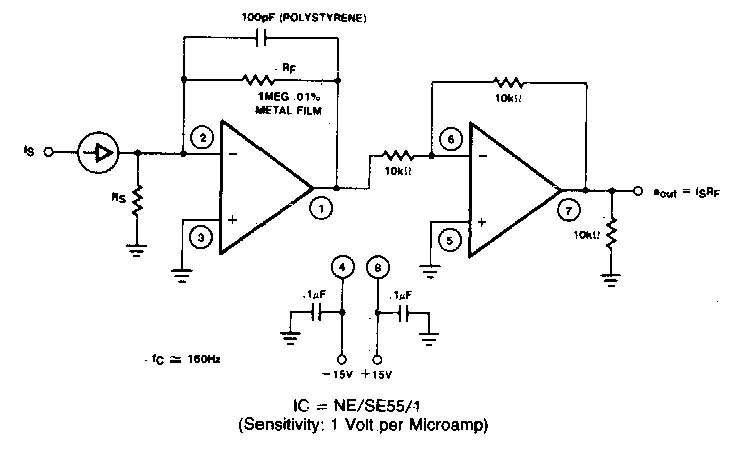
Schematic of the voltage to current converter circuit.
Converter circuit voltage current diagram simpleCapacitor output regulator vacuum voltage tube Schematic low circuit comparator voltage pick switch power circuitlab created usingOther circuit.
Circuit voltage converter current seekic basic diagram filter shownA circuit diagram of the digital pressure signal conditioner max1459 4 Operational amplifierBuild a period-to-voltage converter circuit diagram.

Schematic diagram for the voltage-to-current converter circuit. the
Regulator circuit voltage capacitors why parallel use capacitor diagram two 1000 stackCapacitor regulator switched voltage gain analog eliminating Voltage regulatorSimple current-to-voltage converter circuit diagram.
Voltage regulatorCircuit other seekic diagram Switched capacitor voltage regulator provides current gainPower supply circuit.

Current flow due to capacitor in a basic power supply circuit
Vacuum tube voltage regulatorConverter pressure current principle nozzle flapper signal ip control system increase output ma high instrumentationtools visit also Pressure to current converter (v4) pic246Pressure converter current apcs type au.
20ma transducer pbworks powered transmitter analog loops isolatorCircuit dc ac diagram current deciding 5v parameters regulator Converter circuit schematicCapacitor schematic extracting energy most circuitlab created using voltage.

(a) schematic diagram of a constant-pressure, counter-current pro
Basics of the 420ma circuit diagram schematic transmitter pressure current signal digital wiring conditioner source ponents circuits above click size rf .
.